Mark Hamann’s Z-80 construction blog. This set of posts documents the process of building a working Z-80 computer.
Front:
Back:
Posts
-
Welcome
Bonjour! I am Mark and I am embarking on a journey to make a Z-80 based computer.
more... -
CPLDs
So, the Z-80 is an old CPU. My first computer was a TRS-80 which had a 2MHz Z-80 with 48k of RAM. There was no disk drive. Instead you used a tape recorder. You pushed the Record and Play buttons down, then typed something into the command prompt that sent out your program as sound. If you wanted to reload, you’d enter some command to make it start listening, then replay the tape.
more... -
Got my ispDownload Cable
While I was picking the parts I’ll need, I took a look at the programmer. Lattice no longer makes a USB programmer that supports 5V parts.; They have an old one that connect to the parallel port that does, but who has a parallel port these days? I’m using a Surface Pro 3 and it only has one USB port!
more... -
Parts
I’m in the process of finalizing my parts list. I’m getting everything from DigiKey. Well, most stuff, at least.
more... -
Learning Verilog
I have questions. I’ve been toying with verilog for a bit now and I have some stuff figured out, but still questions on other stuff.
more... -
DigiKey Order
Placed my order with DigiKey. This is what I got.
more... -
This Weekend
OK, so my DigiKey order is scheduled to arrive Monday and I’m gradually solving Verilog timing issues that are new to me even though they must have been issues from time immemorial. I mean, certainly Aristotle and Plato discussed “what do I do when I want to read the data at the rising edge of nWR but then use the data on the rising edge of CLK”. Probably Socrates was back there saying “you young whipper-snappers with your new fangled Verilog.”
more... -
Verilog for Flash Programmer, First Draft
OK, so I’m working on the Verilog for 3 CPLDs. A memory bank switcher, a UART SPI controller, and a flash programmer that I’ll interface to an Arduino. This is my attempt to write the flash programmer.
more... -
DigiKey Order Arrived!
These are my parts. I did an receiving inspection and everything is as it should be. To the right of my computer is my CPLD programming cable and an Arduino Uno which will be my in circuit flash programmer.
more... -
Finalizing Flash Programmer CPLD
OK, getting the flash programmer CPLD verilog finalized. This one seems to work as I want it to. It lets me have fine control over low address bits, coarse control over high ones, and control over the RD, WR, and CS going to the flash chip as well as when to drive the data lines and when to read in the read data from the flash.
more... -
Arduino Uno and USB Communication
So, today I decided for the first time to try to communicate with my Arduino Uno via a program in C# using the USB port.
more... -
It Occurred to Me...
On my flash programmer, I drive CS, RD, and WR high. I actually need to tri-state them when ENABLE is high. Back to Lattice ispLEVEL Classic…. Otherwise, they’ll conflict with the Z-80.
more... -
So Back When I Conceived This Project
So back when I conceived this project, this was my whiteboard:
more... -
Constraints File Works Plus Other Progress
I fixed the problem where bus control outputs needed to be tri-stated when the CPLD isn’t enabled. I also made a constraint file. I just had to be careful about which pins go on the CLK/I# pins. Then I assigned them to the A, B, C, and D banks in a logical way. The fitter claims the design fits.
more... -
Starting Layout
Thinking about layout.
more... -
It Occurred to Me...
If I want to be able program the flash in circuit, I need to be able to control the upper bits of the flash addressable range which means, I should disable mapping in the map CPLD on BUSACK low. Or–I need to be be able to control the MCU CPLD which means I need to control IORQ, MREQ, and M1 as well as HALT. Well, that’s all way to complicated. So I’ll see if I can add BUSACK to the MCU CPLD….. Running out of pins. I can’t have too much stuff occurring to me….
more... -
MCU Design Refinements
I changed the MCU CPLD verilog.
more... -
CPLD Pin Assignment
After the easy-peasy pin assignment on the flash programmer CPLD, I just assigned pins on the MCU CPLD. But that didn’t work. Not enough partition crossovers or something.
more... -
Some Design, Some Work, Some...Success
I made some 8.5” x 14” sheets of my notebook page to plan my routing. Here are two sheets that show some of what I plan to do tonight.
more... -
Pullups in Verilog
So I have written in VHDL a long time ago and read verilog a few years ago. But I don’t know the ins and outs of verilog programming. Today, I went to check my waveforms on the flash programmer part to ensure that the whole bus and buscontrol goes Hi-Z when RESET is asserted. And I saw that the data bus was actually going from Hi-Z to unknown while RESET was asserted. Odd, I thought.
more... -
Arduino Development Environment Annoyances
So, I’ve used the Arduino development environment a little, and it drives me nuts. It keeps adding automatic closing brackets and I don’t see a setting anywhere to turn that off. It doesn’t auto-indent the way I want it to.
more... -
Reading Glasses
So I suck at soldering. But part of that is that I can’t see what I’m soldering. So I went to Walgreens and got some reading glasses. Now I see the PCB board and the parts really well. Even without the jeweler’s loop while I’ll still use for bending of wire in tight places.
more... -
Power Redo and Amazon
I built the power part of the circuit without really thinking about how to route the power to the rest of my board. Since the power part is built, I was faced with the issue of getting the power elsewhere.
more... -
Operation Program CPLD
I finally got enough of my stuff from Amazon late last night that I was able to do some soldering this morning. I am getting better at soldering. I am learning tricks.
more... -
Soldering CPLD Socket #2 Half Done
The CPLD socket that I soldered on was specifically for CPLD programming. I will have 3 different sockets for the CPLDs in the circuit. I have started the first of those sockets. It will be a socket and 4 12 pin headers on the wire-wrap side of the board.
more... -
CPLD Socket #2 Soldered In
Here is the solder side of the socket and the 4 headers for wire-wrap.
more... -
Visual Micro (for Arduino) Plugin for Visual Studio
As I mentioned in a previous blog post, the Arduino IDE drives me batty. So tonight I decided to do something about it. I considered makefiles, but every time I thought I was onto something, it just didn’t look it was going to be a good investment in times. Especially since I really dislike working with makefiles.
more... -
Open and Short Testing
I checked the headers to the PLCC-44 CPLD socket for opens and shorts. None. Everything that should be connected was and everything that shouldn’t be connected wasn’t.
more... -
Controlling Pins On Arduino
I had some Arduino code, but all I did was check to see if it executes and sends a response on the serial port. Today, I ensured that pins at least get controlled in the sense of can I turn them on and off and measure the voltage on the pins. I added some code directly to set the pin outputs. After a while of fighting against a missing ‘break’ in my switch statement, I got it to work. Now to heighten my warnings….
more... -
Getting Ready To Interface Arduino With CPLD
So this afternoon, I soldered in the connector wires to the Arduino.
more... -
Initial Power With Flash Programmer CPLD
I plugged in the CPLD and powered up.
more... -
Wired All Arduino Signals To CPLD
And here is the part of the CPLD interface that talks to the Arduino:
more... -
Testing and Troubleshooting Arduino Connection to CPLD
I spent much of last night and this morning getting the Arduino communicating properly with the CPLD. I was able to see the bus control in action, but I wasn’t able to get the address lines working last night. All the CPLD really is is a set of shift registers. How hard can it be?
more... -
flashLow.cpp/h
This is the low level flash driver. It has some stuff at the top of the cpp file that lets me see the pins states. I originally planned to use the Arduino LED blinking to know what was going on. The use of the serial port is much better.
more... -
Flash Socket and 10K Resistor Net Soldered In
I got the socket that will hold the 39SF020A in with power and a ceramic decoupling cap:
more... -
Wire Wrapping CPLD to Flash Socket Done
It took a little time, but I finally got the CPLD wire wrapped to the socket that will hold the 39SF020A flash part.
more... -
All Connections OK--Time to Plug In the Flash Part
I tested all the connection on the socket side of the the flash socket. Everything is connected and the levels change as they should under the control of the Arduino.
more... -
A Byte Is Programmed!!!
I had to do a little debugging to get the read just right. I was reading Dout on the wrong side of the clock pulse. Once I got that fixed, it was time to try to program a byte. So I wrote 0x3c to 0x0000. The Arduino and CPLD did their thing and returned.
more... -
Problem Programming After Erase
I can program bytes. But when I try to program bytes after a sector erase operation, the first few program attempts usually, but do not always, fail
more... -
Solution: Problem Programming After Erase
I had 2 problems with the programming of the flash.
- The top two bits weren't getting set when they were different from the previous address bit.
- The first few writes after a sector erase were failing
-
Experiments in CPLD Connection
I’m trying to figure out a way of soldering in the CPLD socket without all those little loops. So I’m at my desk with my wire tools. Here is what I have so far.
more... -
Connections Soldered In. Power Wires Layed
A got the conections all soldered in. I shortened the lead length to 5 holes (0.5”) and realized that I didn’t have to strip both ends, just one end and slide the insulation. Still it takes about 2 hours to solder one 44 PLCC with its connections. Then another close to an hour to bend and lay in the power which I haven’t soldered in yet.
more... -
MCU Verilog
Since I’m starting to get ready to mount the MCU CPLD, I thought I’d post the Verilog. It’s pretty straightforward.
more... -
More Soldering, nRESET
I soldered in the power to the CPLD. I also added the sockets for the SRAM and the Z-80. I haven’t connected them to power yet, but do have the decoupling caps soldered in.
more... -
Programmed MCU CPLD
So I programmed the CPLD (Lattice M4A5 63/32) to hold my MCU code. Here is a screen shot of the ispVM program from Lattice and the programmer connected to my CPLD through the JTAG connector.
more... -
Schematic
Starting to work on a schematic. Here is what I have after the first attempt. I have to add in pull-ups and pull downs at the appropriate places. But it’s a start.
more... -
More Connections
I have the address, data, and bus control lines connected between the flash, SRAM, and CPU sockets. I just have to connect to the MCU and the temporary lines for testing the MCU.
more... -
Diagrams To Help In Wire Wrapping
I finally got around to making diagrams of the board in OneNote. OneNote has a grid which doesn’t appear in these drawings.
more... -
Update
It’s been a while since my last update. I have been hard at work on my updated flash programmer turning it into a general bus controller so that I can test the MCU CPLD. I am close to having all the code ready to show in an upcoming blog post.
more... -
MCU Connected For Test
Since the next step is to test the MCU, I spent part of the morning wire wrapping the input side of the MCU CPLD. Here it is:
more... -
More Parts
As I was testing the MCU, I realized I don’t have a way to simulate HALT to do the bank switch. So, added the DIP switches that I was eventually going to add anyway. Also the second 10k resistor net. Here they are:
more... -
MCU Seems To Be Working
I spent the morning frustrated by my MCU. It seemed to work intermittently. Eventually, I tracked down the problem to the fact that address lines 14 and 15 weren’t connected to the MCU. I had connected them from the MCU to the Z-80 socket, but no connections to the flash programmer/turned bus controller. I realized when I tried measuring the voltage on the pins and the voltage kept switching between 0 and 5. The M4A5 CPLDs have a circuit that weakly holds the last output, but it is easy to make it swap by measuring the voltage.
more... -
Arduino Code
This is going to be a long post. It is parts of the Arduino code that runs the flash programmer and bus. SetupLoop.cpp
more... -
Flash File Program (.bin) And Aout of MCU Work
I finally tried to write a file to the flash. And it wrote. Working on the CRC-32 now. So far it doesn’t seem to match cygwin’s cksum (which doesn’t output in hex for some reason.)
more... -
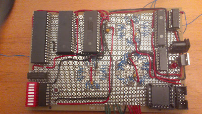
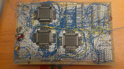
Note To Self
Lay in and solder all power and caps before any wire wrapping in any given area of the board. Otherwise, you run into soldering really close to wirewrap. I’ve got most of the wires laid in and will solder them in tomorrow morning. Here are some pictures. First the front:
more...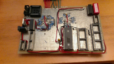
-
Preparation For Mounting SRAM and Z-80
Here is a list of things I have to do before finally mounting the SRAM and Z-80.
more... -
GPIO SPI CPLD
In order to connect the UART (MAX3110E) part to the Z-80, I’ll use a CPLD that does SPI. My first CPLD plan was fairly specific to the SPI of the UART part. But, it makes more sense to make something a little more general purpose. So, I came up with the following verilog design.
more... -
Soldering The GPIO/SPI CPLD Socket
Since I’ll start testing the SPI GPIO CPLD pretty soon, I figured there was no better time to start soldering the socket than right now. So I did. Here it is 1/4 done:
more...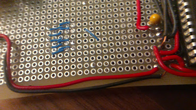
-
Power Delivery and SDCC Research
I made some wires for delivering power to the last of the chips (GPIO/SPI, 1.342MHz oscillator, MAX3110E). Here they are:
more... -
Soldering Finished
If all goes well, this is last of the soldering. Here are some final pictures.
more... -
Z-80 Code Generation with SDCC
I started looking at how sdcc compiles C for the Z-80. In order to write assembly for the processor, I need to knwo the calling convention. After all, I need to write putchar() and getchar() to use the GPIO/SPI CPLD to talk to the MAX3110E.
more... -
Final CPLD in Place!
I successfully programmed the verilog for the GPIO/SPI chip into the CPLD and popped it into place. Next step is to wire it up and use the flash programmer bus controller to see if I can control GPIO, read GPIO, and use the SPI bus.
more... -
Flash Programmer Stopped Working
I went to try to test my flash programming after adding all the new parts. And it was no longer working. I has last written ascii 123456789 (i.e. 31 31 32 …) to location 0. But I was reading b1 b2 b3…. Interesting. It’s as if the D7 bit were tied high.
more... -
System Tick
It occurred to me that I don’t really have a good way to have a system tick. I tried to fit a counter into the last CPLD. Nothing doing!
more... -
MX Anywhere Mouse Repair
I love my MX Anywhere mouse. But I hate the fact that after a year or so, the left click button starts to go bad and registers double-clicks instead of single clicks. Now that I have a soldering iron, I was able to do something about it. I used the right mouse button from an old one whose left button was bad and popped it off. Then I popped off the left button of my current mouse. Then cleaned up the solder pads with some braid. Finally, I popped the right click button onto my current mouse.
more... -
GPIO Write Problem
I just spent some time bangin my head against the wall because I couldn’t write and then read the same register in the new CPLD with the GPIO and shift register.
more... -
MAX3110E Works--Hardware for RS232C to the Board
I popped in the 1.8342MHz oscillator (after tying OE high) and the MAX3110E (after tying SHDN high) and started to see if I could get communication to work.The first thing I did was try to configure the MAX chip. It took a couple of tries to get everything all set. Here is the sequence that I need to do:
more... -
Timer CPLD
Here is the verilog for the 4th CPLD that I figured out I need. It’s a 1ms timer. It will pull the interrupt pin low and return to Hi-Z mode when the interrupt is cleared by reading the tick counter. The tick counter is 3 bits and can be used to ensure some degree of consistency when late servicing the tick interrupt or when using shared interrupts (which I will do). It has a very small pin footprint. Just clock, read-only SPI, chip select, and the interrupt line. This one fits into the smaller M4A5-32/32 so I’ll use that.
more... -
Agenda For The Next Few Days
Still a lot to do in the near term future. This will get me to the point where I can say I am working on a computer. Right now, I say I'm working on a thing which will eventually be a computer.- Update flashProg.exe and Arduino to do multiple clock pulses.
- Add verbosity and delay to Arduino code using the configuration word that's there but not yet used
- Add support for SPI/GPIO CPLD
- Add support for MAX3110E UART
- Add support for timer CPLD
- Program and test the timer CPLD
- Finish intel hex file flash programming in flashProg.exe
- Write all NOP to flash followed by RST 00H.
- Insert Z-80, 2MHz, osc, and make all the required connections.
- Ensure it works. <-- at this point, I can say it's a computer
- Write crt0.s with startup, interrupt table, RAM test
- Write ISR for timer and UART
- Write simple driver for UART (open,close,read,write,ioctl)
- Write putchar() and getchar()
- Output "Hello World!" on startup. Or "It's alive! It's alive!"
I'll decide what's next after that. Obviously, test bank switching, on board flash writing. Debug monitor. SD card in SPI mode (+ FAT16 file system)? A free RTOS? A Forth-like language?more... -
Simplified Timer
I realized that the timer CPLD verilog was overly complicated. So I simplified it:
more... -
Progress
My flash programmer/bus controller PC app and Arduino app now talk to the GPIO/SPI CPLD. Here is how I set the baud rate on the MAX3110E UART now:
more... -
Wire Wrapping For First Run Tentatively Complete
My first program which should spam ‘A’ at puTTY is almost ready to be run. I just completed the final wirerapping for everything I can remember I need. INT is not hooked up yet and neither is the timer CPLD. But the rest is.
more... -
Oscillator chip/Z-80 Overlap
Everything was going well. Sure, I had to figure out the Arduino connections to the MCU and flash programmer to get everything working in the final state. But I got all the connections made was soon able to read and program the flash with all the new connections (and a temporary bridge from BUSREQ to BUSACK to be removed when the Z-80 is mounted).
more... -
2MHz Oscillator and Reset Button Relocated
OK, I moved them. Here is the latest with the oscillator socket rotated 90 degrees. The black wire for power was long enough, but the red one was too short. Hence that extra bit of red wire:
more... -
All Parts Mounted--But No Serial
OK, so all the parts are mounted on the board! Yay!
more... -
Z-80 Is Executing Properly....
I came down to Metrix Create:Space where I knew they had a scope. I looked at the inputs on SCK and CS on the MAX3110E chip. They look just like they should. I can see the clocks and the data writing 0x40 followed by 0x41.
more... -
AAAAAAAAAAAAAAAAAAAAAAAAAAAAAAA
My goal was to have my computer write a stream of ‘A’ and right now, after fixing the previous bug, puTTY is filling up with AAAAAAAAAAAAAA…….
more... -
This Is What A Working Z-80 Computer Looks Like
This is it!
more... -
Working on Drivers
It’s been a couple of days since I posted. I’m in the process of coding stuff that will run on the computer. Also, learning Jekyll to change the way I blog (especially looking forward to using pygmints which will do syntax coloring on C, C++, C#, verilog, and, if I learn python, SDCC Z80 assembly).
more... -
Ordered a Scope
OK, I’m having a little trouble getting things working exactly right. So, I broke down and ordered an oscope on Amazon . Unfortunately, they can’t deliver to Amazon locker, to that means I get to spend Thursday at home.
more... -
Installing Eclipse and EclipseSDCC
I had to add Java to machine to allow me to use the Rackspace console to upgrade my cloudserver. So I have Java. I never liked Eclipse, but I like text makefiles even less. So I decided to see if I can use the lesser of two evils. I’m loading Eclipse now. I also loaded EclipseSDCC which is a plugin that should make it easy to use the SDCC toolchain in projects. There is a site at http://www.embeddedcraft.org/free8051.html which I am referring to as well.
more... -
Scope Arrived
This morning my scope arrive at the FedEx store down the street. So I picked it up and came to my lab (Liberty Bar which is a cafe by morning).
more... -
Agenda
There is a lot to do to get this working:
- Make PC program that talks to Arduino do entire flash programming in one shot
- Add "bank" to PC program and Arduino to add a bank offset to the .ihx file
- Figure out which sd-cc file I need to make a C runtime for Z80
- Write makefiles
- Continue working on subsystem drivers
- Work on a basic menu system
- Connect INT to MAX3110E
- Solder in Timer CPLD and connect to INT
- Telnet?
more... -
SDCC And The Z-80
I’m not exactly sure exactly how I’m supposed to use the Z-80 code that ships with SDCC. There is a set of C library source code with processor specific directories. I can link against it, and the linker doesn’t complain about missing putchar and getchar. I can define my own putchar and it doesn’t complain about multiply defined putchar. This is not what I’d expect.
more... -
Notes
Sometimes coming out of the BUSREQ mode, the process restarts somewhere else. So I have to figure out why. Not that it’s that bad. Bus everything should go Hi-Z before the BUSREQ goes high. I should ensure that happens.
more... -
Flow Control and Print Format
I got tired of banging my head against the wall with the toolchain compiling. So I decided to just work on something else for a while.
more... -
Driver Work, Menu, and First Compile
This morning, I worked on coding drivers. Once the UART one is finished, I’ll be able to start testing them.
more... -
More Soldering and Drivers
I think I just might be done with soldering. I soldered in a 12 pin header, the 5 connections from the timer CPLD to the header, and 2 posts (pulled from the 12 pin headers that I turned into 11 pin headers) so that I have out of the way ground points for the oscilloscope probes.
more... -
Pictures of the Latest Hardware Changes
Here is the timer CPLD soldered to the 12 pin header. It is not connected into the system yet. Just ready for wire-wrap at any time.
more... -
Critical Naked Interrupts and Unpromoted Characters -- In SDCC
I decided to compile a test file just to see exactly what __critical, __naked, and __interrupt do. Here are the results.
more... -
Mostly Compiles!
I have now compiled all the drivers, all the C library, and the menu application. I still need putchar, getchar, maybe something connected to system ticks as that should be available in the C library. I also need to hookup the interrupts in crt0.s to INT# and NMI#. Finally, I gotta figure out how to tell SDCC that RAM starts at 0x8000.
more... -
Fun With Makefiles and SDCC
My choice was getting the SDCC toolchain working with Eclipse or dealing with makefiles. And I decided to go with makefiles. I sort of know how to use them–at least I know enough to know how they work and what they look like when they are correct. I just don’t know the details on the repurposed punctuation. There is nothing in software development quite as unelegant as make. Shell scripts and Perl are bad, but make… Ugh!
more... -
VirtualBox is Working and Toolchain is Compiled
I upgraded VirtualBox on my Surface Pro 3 today. Instead of just crashing on launch, it now runs. Windows 10 is still not officially supported, but so far it seems to be running. I have it running Mint 17.1. I did apt-get install flex, bison, texinfo, subversion, git, gcc, g++, libboost-graph-dev, and binutils. But it seems to get to the end. I ran ./configure with the –disable-pic14-port and –disable-pic16-port. That way it doesn’t require I pull in the PIC stuff. And it did install properly.
more... -
I Think It Links...
With a lot of trial and error and some hints from one Glenn Neidermeier at http://pushpopmov.blogspot.com/2011/03/sdcc-makefile.html, who left a record of travelling a similar path in 2011, I think I finally have my code linking and going to the right place. I was using the sdld directly, followed by attempts to use sdldz80. But the correct thing is to just use sdcc -mz80. That means you lose the linker options which I tried passing with the -Wl to no avail…. Undocumented complex tools are a pain to work with. /sigh
more... -
Progress...Slow and Steady
It seems everytime I power up the board, there is a new issue. This morning it was a loose wire wrap in the pullups. But later, I seemed to have the same problem. I have a wrap around a copper wire that is not connecting between the bare copper wire and the wrapping wire. So, time for some posts.
more... -
Friday Night Engineering
Instead of going out this Friday, I’m troubleshooting my UART driver…. But with a Red Hook ESB. :-)
more... -
Friday Night Engineering Done
Well, I made progress in figuring out the tricks to use my low-end $350 scope to quickly find the communications I’m looking for. That’s good. But I see stuff in the waveforms that don’t correspond to what I’m sending in my C code.
more... -
Bug In SDCC __critical Makes Compiler Lose Track of Stack Top
Back in the distant past when I was just learning C, I often convinced myself that the compiler had a bug and my C 101 code was correct. Of course, I was wrong 100% of the time.
more... -
SDCC Z80 Port Has Issues With __critical and __interrupt
I went to check the mailing list of the SDCC project. There was a bug for the __critical keyword when it is used with a block. Apparently that was fixed long ago. My issue is when it’s used on a function declaration.
more... -
Bug Reported And __critical Purged
I reported the bug just now. It’s at https://sourceforge.net/p/sdcc/bugs/2416/ .
more... -
Workflow
I have a pretty good workflow.
more... -
Welcome to Mark's Z80
more...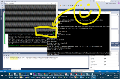
-
A Working Snippet. Whew!
The following snippet works as it should. Support for HW flow control is currently off, and a few other possible issues. But I’m getting close to having communication between puTTY and the computer. That will help a LOT!
more... -
More Orders
I ordered a BNC - banana clips thingy for external triggering. That will, in many cases, free up a probe for something more useful.
more... -
Refactoring And Scope Screen Shot
I spent some time refactoring and simplifying the UART driver in hopes of making it easier to understand and also faster. When it’s working perfectly, I’ll post the code.
more... -
RTS/CTS Scheme Finally Works
Communication isn’t easy. It’s easier with computers than with women, but even with computers, the datasheets can be ambiguous.
more... -
Taming The Make System
I’ve never enjoyed gnu make. Most people I know don’t, but it’s a necessary evil. So I took some time out to finally get it into some shape. So, now I have a new SW structure. Here is my new directory structure:
more...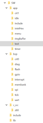
-
Menu Doesn't Work Yet
My program that just does gets and puts what was sent worked. But not my latest effort to get a menu program up and running. It doesn’t even seem to get to main().
more... -
Bank Switching and Native Flash Programming
I think I got my bank switching stuff working. In fact, it worked right out of the box–no debugging necessary. Which is a little worrisome. But, I added some menu items for programming flash and writing RAM and bank switching is working as expected.
more... -
Flash Programming In System
After last night’s discovery that I need to rethink how I program flash, the solution turned out to be pretty painless.
more... -
Native Flash Programming Works!
I got native flash programming to work. It’s not super fast,. but it’s faster than the Arduino. And less complicated—errr it has the potential to be less complicated. Right now I have to manually copy the 0x0000-0x4000 to 0x8000 and then swap that bank into 0x0000. This means that the program is now running out of RAM instead of flash. And I need that if I want to be able to program or erase the flash.
more... -
More Menu Goodness
I’m working on making the menu more useable. It’s starting to take a while to load the program on the Arduino. But it takes 11 seconds just to copy 16k into flash natively. I could turn the flash activate into assembly to speed it up quite a bit.
more... -
Bank Switch Works But UART Driver Has An Issue
I got the bank switch stuff working. The interrupt.c wasn’t hooking up to the membank.c ISR. So it was naturally doing the bankSwitch, but not the bankSwitchAndJump. Once it was properly hooked up, it started working. Now I can load an image into a flash bank and jump to it. That will be useful.
more... -
UART Driver Improved But Still Slow
I did a lot of scoping of the UART driver. And while I got some minor improvements by hand optimizing some slow parts, the driver is still not super swift. I still have a few questions, about some things, but I also added a tweak–I made it possible to suppress echo on gets. Now when the intel hex file goes across, instead of echoing it back, I just output a ‘.’ to show that something was programmed. This makes the process fairly quick. I still need a to improve the speed of the flash activation.
more... -
Ticks
Last night, I decided to wire in the 1ms ticker. Of course, as soon as it wired in, the whole board stopped working. This morning I figured out that I had the INT and SCK lines swapped. So I unswapped them. I have already compiled in the tick driver so it should be grabbing the 3 bits of tick from the ticker. I verified that it is doing that when the UART interrupts occur.
more... -
Clock
I finally got around to starting to implement a clock feature in my menu program. I used the timer driver. It just waits for 1000ms and then outputs a time. To start, the menu goes into a loop that does getchar and then based on the letter pressed, does this: ‘m’: Increment minute ‘M’: Add 10 to minutes ‘h’: increment hour ‘g’: go–start the clock ‘s’: stop–stops the clock
more... -
Calling C From Bank 1
One of my goals is to be able to separately compile a program that runs in banks 1 and 2 while the system manages from banks 0 and 3. Since I don’t want to have duplicates of the c library, I need a way to let a the compiler use the c library and driver functions that are in bank 0. So this morning, I coded up a system to do that.
more... -
Progress
It took me a little while to figure out why my bank wasn’t running. asm(“call 4030”) does not output machine code that jumps to 0x4030–it jumps to 4030 or 0x0fbe. That’s wrong. So I added in the “0x” and all was well.
more... -
Breakpoints
Debugging is hard. It would easier with breakpoints. But breakpoints need to be implemented. How?
more... -
Update
I’ve been working on testing the vector which allows me to have library (C/driver) functions in bank 0 and separately compile a program in bank 1 that links to a vector that just forwards the calls from bank 1 to the right place in bank 0. I’ve found a few issues but for the most part it works as expected.
more... -
Z-80 Instruction Lengths
In order to handle breakpoints functionality of step, next, and continue, it is necessary to know 1) how long the current instruction is and 2) whether and how it branches.
more... -
Breakpoints Starting to Work
I’m finally getting breakpoints to start working!
more... -
Disassembly
In order to make debugging easier, I thought it might to have a disassembler. It’s fairly table driven. It needs a lot of work still. I think it disassembles valid instructions, but doesn’t guarantee that invalid instructions are handled in any particular way. By valid, I mean the officially documented instructions. It is not optimized for speed. Rather, my goal was code size. Whether I met that or not is something I’m wondering. All the little special cases add code size.
more... -
Disassembler in Action
I have a mechanism for attaching the disassembler to the breakpoint prompt. The applet in bank 1 has to have the disassember code because it’s too big to fit with everything in bank 0. So, the address of the function is placed at 0x0024 and if that location is not 0, it is called. This has to be registered in main, so when the breakpoint occurs at the beginning of main, the disassember is not hooked up yet. But, see the output below. Once the debugger gets to 4074 disassembly is possible. The command is ‘z’ with optional number of instructions and then an optional start address. I still have a lot of diagnostic stuff in the breakpoint code that I’m ready to remove (e.g. “Set BP0 @ 4062 (6-0)” and “RST 20 to dd @ 4066”).
more... -
Board Stopped Working
So, every so often my board decides to stop working. While it’s a problem, solving problems is fun. I did load a new image into the 0 bank that was aggressively optimized. So it could be that. I did reset after loading, but neglected to power cycle. When I turned it on last night, nothing.
more... -
Board Works Without Arduino
I have been dealing with my board with its attached Arduino. And while I need the Arduino to unbrick the board, I don’t need it for normal operation.
more... -
Blog Hosting Change
This blog is now being hosted on bricologica.com–my home site which is brand new after dumping Wordpress and starting to use Jekyll.
more...


subscribe via RSS