Getting Ready To Interface Arduino With CPLD
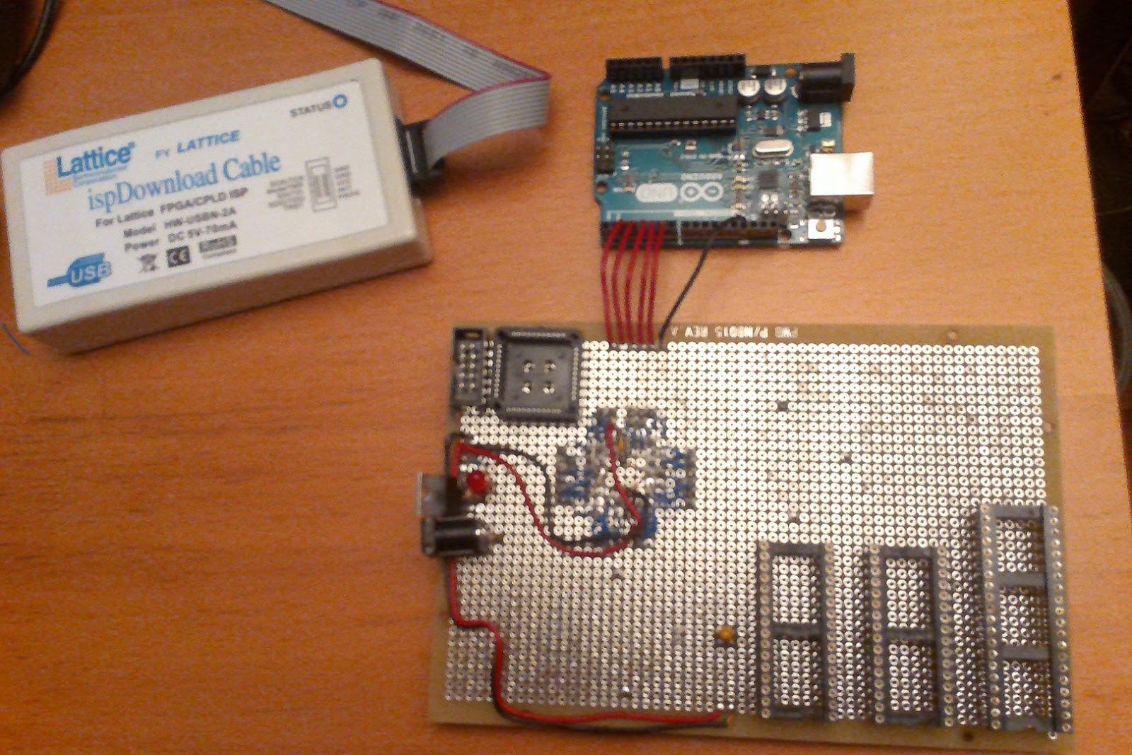
So this afternoon, I soldered in the connector wires to the Arduino.
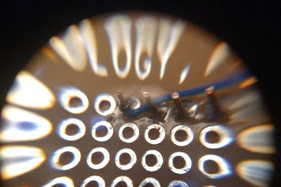
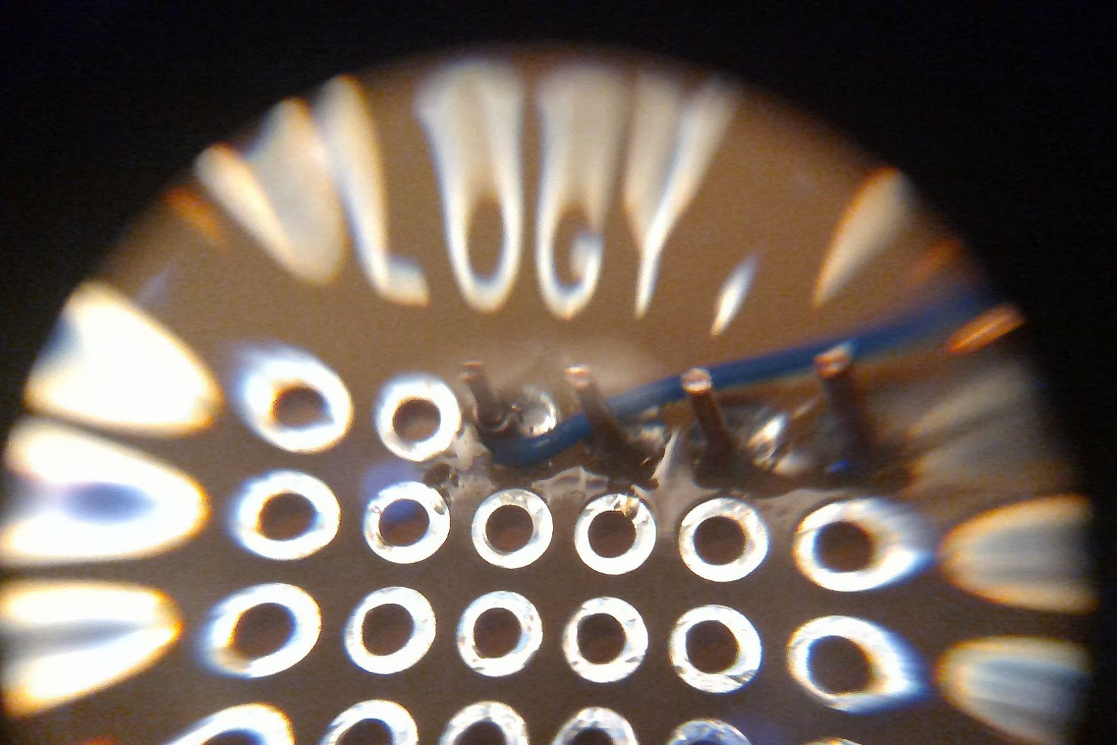
The ground connection to Arduino goes through my first wire wrapped connection:
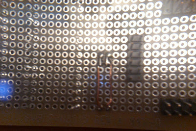
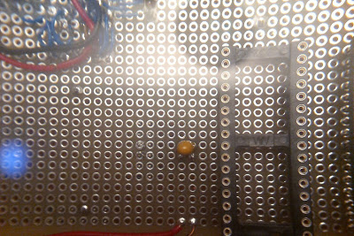
I also have to think about power delivery. So I soldered in two pieces of wire Here are the front and back. The two rails of copper wire in the upper picture run along 5 holes which will take other wires so they can be connected. The lower picture shows the other side with a tantalum capacitor that will keep the 5V close to 5V under sudden loads.
 The IC sockets are not soldered in. They are just there for visualization. The one closest to the CPLD socket that's soldered in will be where the 39SF020A flash part will be mounted once I've established the CPLD is behaving the way I want it to.
Tomorrow, I'll make sure that the CPLD powers up and that the inputs look like they're floating. Then I'll wire wrap the Arduino wires to the CPLD and see if I can control the CPLD outputs as I expect. A scope or logic analyzer would help, but I'll just get creative since I have neither. Probably, I'll add a mode to my Arduino code that will let me single step through the operations. Or maybe just slow them down so my multimeter can see signals changing.
The IC sockets are not soldered in. They are just there for visualization. The one closest to the CPLD socket that's soldered in will be where the 39SF020A flash part will be mounted once I've established the CPLD is behaving the way I want it to.
Tomorrow, I'll make sure that the CPLD powers up and that the inputs look like they're floating. Then I'll wire wrap the Arduino wires to the CPLD and see if I can control the CPLD outputs as I expect. A scope or logic analyzer would help, but I'll just get creative since I have neither. Probably, I'll add a mode to my Arduino code that will let me single step through the operations. Or maybe just slow them down so my multimeter can see signals changing.

