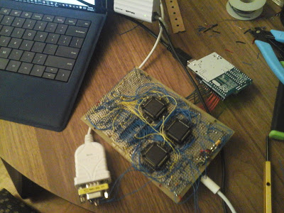
MAX3110E Works--Hardware for RS232C to the Board
I popped in the 1.8342MHz oscillator (after tying OE high) and the MAX3110E (after tying SHDN high) and started to see if I could get communication to work.The first thing I did was try to configure the MAX chip. It took a couple of tries to get everything all set. Here is the sequence that I need to do:
flashProg.exe reset <-- prep Arduino
flashProg.exe pins 1 <-- prep Arduino

flashProg.exe wp16 80 1
flashProg.exe wp16 81 1 <-- CS# GPIO output enable
Then this code sets the baud rate top 9600:
flashProg.exe wp16 81 1
flashprog.exe wp16 80 0 <-- CS# low
flashprog.exe wp16 83 c0 <-- c0 means write configure
flashprog.exe wp16 84 28 <-- shift out 8 bits of '83' toward MSB

flashprog.exe pinwrite 1000 0 <-- clock pulses
flashprog.exe pinwrite 1000 1000
flashprog.exe pinwrite 1000 0
flashprog.exe pinwrite 1000 1000

flashprog.exe pinwrite 1000 0
flashprog.exe pinwrite 1000 1000
flashprog.exe pinwrite 1000 0
flashprog.exe pinwrite 1000 1000

flashprog.exe pinwrite 1000 0
flashprog.exe pinwrite 1000 1000
flashprog.exe pinwrite 1000 0
flashprog.exe pinwrite 1000 1000

flashprog.exe pinwrite 1000 0
flashprog.exe pinwrite 1000 1000
flashprog.exe pinwrite 1000 0
flashprog.exe pinwrite 1000 1000

flashprog.exe pinwrite 1000 0
flashprog.exe pinwrite 1000 1000
flashprog.exe pinwrite 1000 0
flashprog.exe pinwrite 1000 1000

flashprog.exe pinwrite 1000 0
flashprog.exe pinwrite 1000 1000
flashprog.exe pinwrite 1000 0
flashprog.exe pinwrite 1000 1000

flashprog.exe pinwrite 1000 0
flashprog.exe pinwrite 1000 1000
flashprog.exe pinwrite 1000 0
flashprog.exe pinwrite 1000 1000

flashprog.exe pinwrite 1000 0
flashprog.exe pinwrite 1000 1000
flashprog.exe pinwrite 1000 0
flashprog.exe pinwrite 1000 1000

flashprog.exe pinwrite 1000 0
flashprog.exe pinwrite 1000 1000
flashprog.exe pinwrite 1000 0
flashprog.exe pinwrite 1000 1000

flashprog.exe pinwrite 1000 0
flashprog.exe pinwrite 1000 1000
flashprog.exe pinwrite 1000 0
flashprog.exe pinwrite 1000 1000


flashprog.exe rp16 83 <-- read the first 8 bits shifted in

pause 2

flashprog.exe wp16 83 a <- 0a is the baud rate scale value plus other stuff
flashprog.exe wp16 84 28 <- 28 shifts 8 bits of '83' out toward MSB

flashprog.exe pinwrite 1000 0
flashprog.exe pinwrite 1000 1000
flashprog.exe pinwrite 1000 0
flashprog.exe pinwrite 1000 1000

flashprog.exe pinwrite 1000 0
flashprog.exe pinwrite 1000 1000
flashprog.exe pinwrite 1000 0
flashprog.exe pinwrite 1000 1000

flashprog.exe pinwrite 1000 0
flashprog.exe pinwrite 1000 1000
flashprog.exe pinwrite 1000 0
flashprog.exe pinwrite 1000 1000

flashprog.exe pinwrite 1000 0
flashprog.exe pinwrite 1000 1000
flashprog.exe pinwrite 1000 0
flashprog.exe pinwrite 1000 1000

flashprog.exe pinwrite 1000 0
flashprog.exe pinwrite 1000 1000
flashprog.exe pinwrite 1000 0
flashprog.exe pinwrite 1000 1000

flashprog.exe pinwrite 1000 0
flashprog.exe pinwrite 1000 1000
flashprog.exe pinwrite 1000 0
flashprog.exe pinwrite 1000 1000

flashprog.exe pinwrite 1000 0
flashprog.exe pinwrite 1000 1000
flashprog.exe pinwrite 1000 0
flashprog.exe pinwrite 1000 1000

flashprog.exe pinwrite 1000 0
flashprog.exe pinwrite 1000 1000
flashprog.exe pinwrite 1000 0
flashprog.exe pinwrite 1000 1000

flashprog.exe pinwrite 1000 0
flashprog.exe pinwrite 1000 1000
flashprog.exe pinwrite 1000 0
flashprog.exe pinwrite 1000 1000

flashprog.exe pinwrite 1000 0
flashprog.exe pinwrite 1000 1000
flashprog.exe pinwrite 1000 0
flashprog.exe pinwrite 1000 1000


flashprog.exe rp16 83 <-- reads the second 8 bits shifted in
flashProg.exe wp16 80 1 <-- <span style="text-decoration: overline;">
CS</span>
high
I had some trouble at the beginning with the actual communication. To start, I connected the RS232C lines to the RX and TX pins of the MAX3110E. Oops. They actually take the 0-5V IO from the buffers (RS232C-TTL inverters) that also live in the MAX3110E. I was supposed to go through those and then to RX and TX. I think I had mechanical connection problems with the port (just sticking wires into holes on the M/F gender changer). And, of course, I was afraid I might have fried the RX and/or TX ports.
So I backed up to do what I should have done. Work in stages instead of trying to get it all at once.
I routed RX to TX and sent data (replace the flashprog.exe wp16 83 c0 with flashprog.exe wp16 83 80) and flashprog.exe wp16 83 a with flashprog.exe wp16 83 30) where 30 is the digit ‘0’. And indeed, I received the data I sent. So I knew RX and TX weren’t fried.
Then I connected RX and TX to the buffers and tied the other ends of the buffers together. Again, I received the data I sent. So I knew the buffer circuits weren’t fried (at not totally fried).
Then I tried to just receive on the RS232C from puTTY. I was finally able to get data. Finally, I connected the transmit side up. And ‘0’ popped up on puTTY’s screen. Just as I’d hoped.
Finally, here is a picture:
