Power Redo and Amazon
I built the power part of the circuit without really thinking about how to route the power to the rest of my board. Since the power part is built, I was faced with the issue of getting the power elsewhere.
I realized that I should have planned this out before I started soldering. So, tomorrow, I’ll disassemble the circuit and start over. This time, I’ll use two long wires–1 red and one black. Red will be Vcc and black will be ground. I’ll strip off insulation in the middle and make little loops. I’ll bring the resistor and LED into the board. I’ll set up the entire wiring scheme before I solder and leave long wires that can connect to other posts that I need to power. Once all that bending is done, then I’ll resolder.
I ordered a few tools I need to so all this from Amazon and it was supposed to arrive by 8pm today. It didn’t so I contacted them via chat and got a $10 credit to use at Amazon. I told them I need the shipment in the AM. If it doesn’t arrive in the AM, I’ll contact them again and try to pry another $10 from them. If it does arrive, I’ll just be happy.
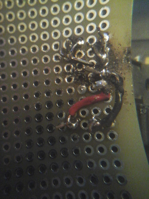
If you’re wondering how bad I suck at solder, here is the solder side of the board taken through a 4x lens held up to my tablet camera:
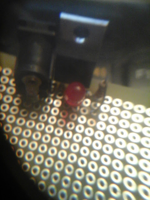
And here is the component side:
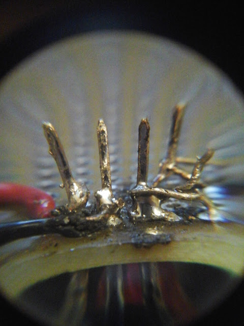
Here are the pins of the regulator with the jeweler’s loop held up to the camera:


