More Soldering, nRESET
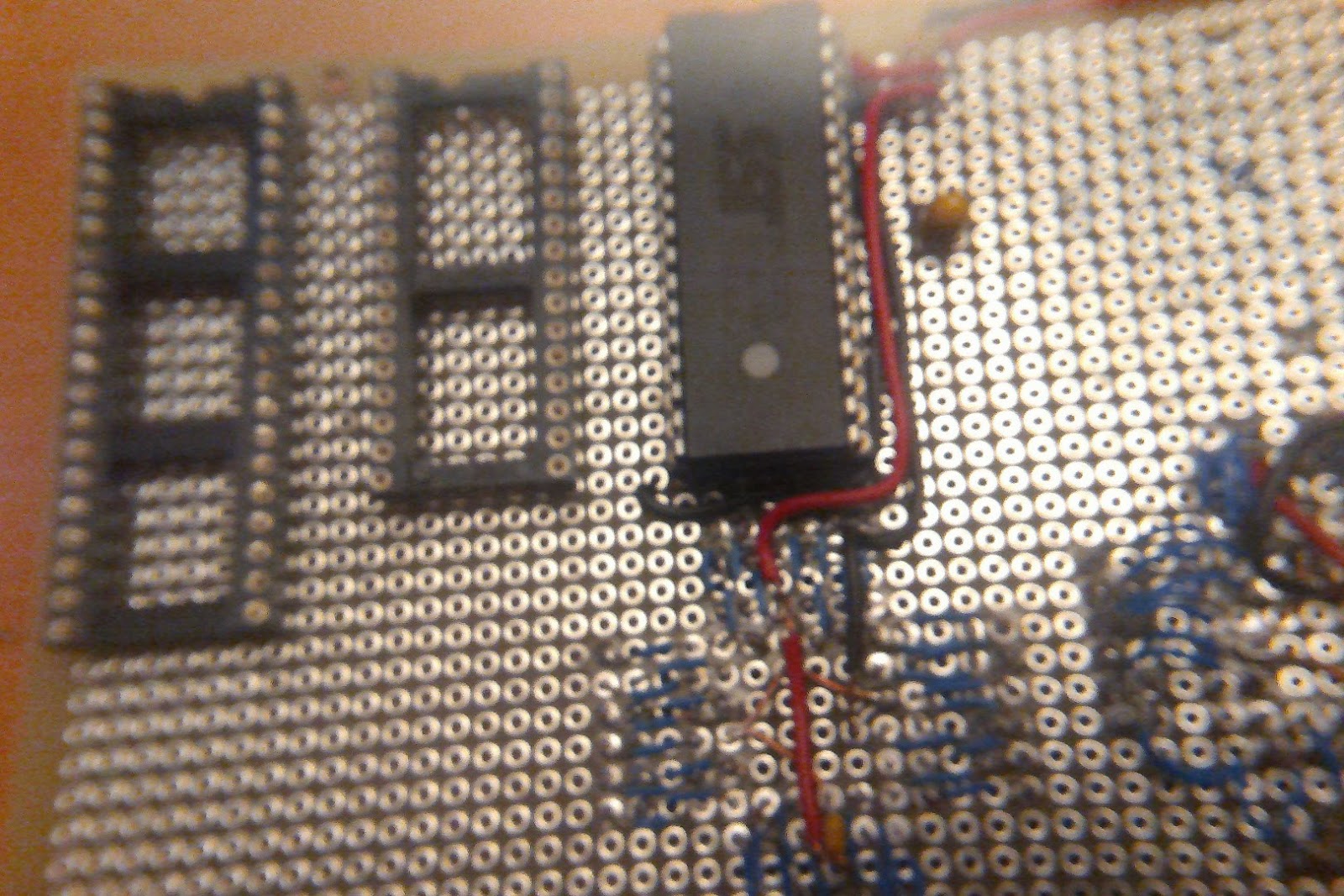
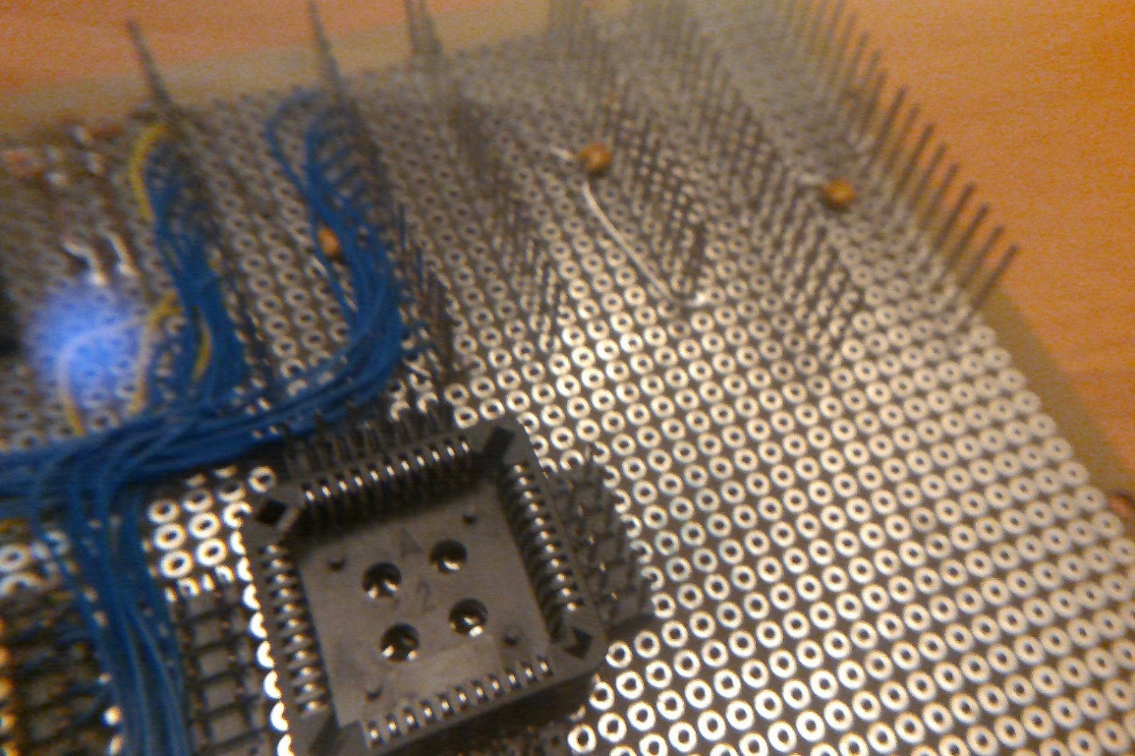
I soldered in the power to the CPLD. I also added the sockets for the SRAM and the Z-80. I haven’t connected them to power yet, but do have the decoupling caps soldered in.
Here are some pictures:
 So, the next step is to make sure it powers up, then program another CPLD with the dedicated CPLD programmer, then start testing. To test, I've decided to use the flash programmer. I'll bring over some extra pins from the Arduino to control, temporarily, CLK, IOREQ, MREQ, M1. I can use DIP switches temporarily for HALT, RESET, and BUSACK. If I run out of pins. I can also use A16 and A17 if I don't have enough Arduino pins.
By the way, I just checked to see if I can use pins 0 and 1 on the Arduino UNO. There is a little text on the connector that indicates that they are RX and TX. And yes, they are the same RX and TX that go the the UART. So, if I want to use the Arduino Serial object, I have to forego pins 0 and 1. Pin 13, of course, is also the LED. So I have 2 through 12. Eleven pins. Should be enough. I'm only using 5 (Enable, Clock, Control, Din, Dout). So (clk, IOREQ, MREQ, M1, HALT). I'll use A16 and A17 for RESET and BUSACK.
Now that I think about it, I need to ensure that the flash chip doesn't drive the data lines. That means I need to ensure that either RD or CS never reach it. Simple enough--don't use CS. I'll need a slightly different Arduino program.
All the prep and testing will take a little while. And since I'm about to do some camping in Wisconsin and I want to travel light from Seattle, I'm at a good stage where I won't need too much of my laboratory once the CPLD is programmed. I'll bring my wirewrap tools: wire, wrapper, cutter, stripper (at 7.25" it's right at the 7" TSA limit for tools I can carry on. I hope it won't be an issue (depends on how they round and if they are ridiculous). I have neither the desire to hijack the flight nor the ability to do it with a pair of 7.25" wire strippers.)
So, the next step is to make sure it powers up, then program another CPLD with the dedicated CPLD programmer, then start testing. To test, I've decided to use the flash programmer. I'll bring over some extra pins from the Arduino to control, temporarily, CLK, IOREQ, MREQ, M1. I can use DIP switches temporarily for HALT, RESET, and BUSACK. If I run out of pins. I can also use A16 and A17 if I don't have enough Arduino pins.
By the way, I just checked to see if I can use pins 0 and 1 on the Arduino UNO. There is a little text on the connector that indicates that they are RX and TX. And yes, they are the same RX and TX that go the the UART. So, if I want to use the Arduino Serial object, I have to forego pins 0 and 1. Pin 13, of course, is also the LED. So I have 2 through 12. Eleven pins. Should be enough. I'm only using 5 (Enable, Clock, Control, Din, Dout). So (clk, IOREQ, MREQ, M1, HALT). I'll use A16 and A17 for RESET and BUSACK.
Now that I think about it, I need to ensure that the flash chip doesn't drive the data lines. That means I need to ensure that either RD or CS never reach it. Simple enough--don't use CS. I'll need a slightly different Arduino program.
All the prep and testing will take a little while. And since I'm about to do some camping in Wisconsin and I want to travel light from Seattle, I'm at a good stage where I won't need too much of my laboratory once the CPLD is programmed. I'll bring my wirewrap tools: wire, wrapper, cutter, stripper (at 7.25" it's right at the 7" TSA limit for tools I can carry on. I hope it won't be an issue (depends on how they round and if they are ridiculous). I have neither the desire to hijack the flight nor the ability to do it with a pair of 7.25" wire strippers.)