7 Segment Rainbow
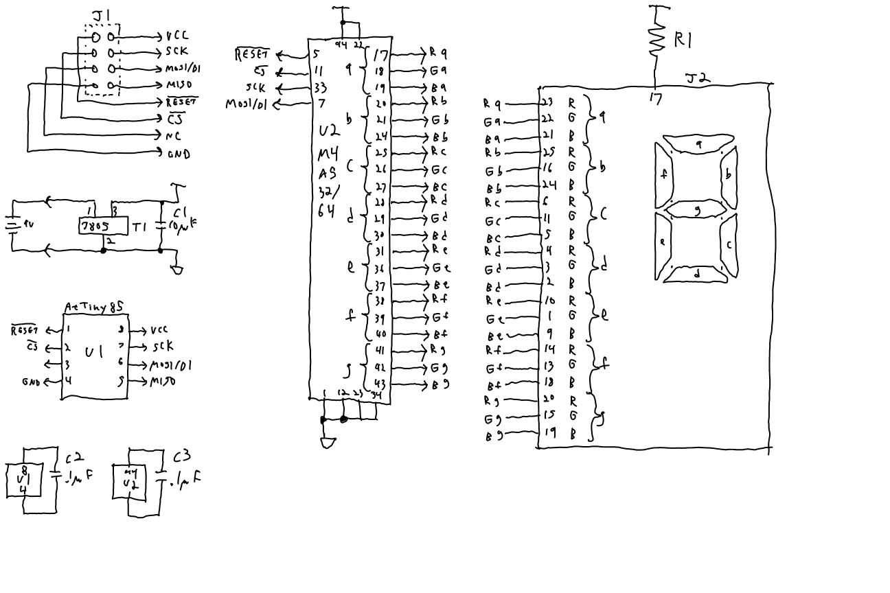
My friend, J, has this 7 segment RGB display from Adafruit. She plans to make each segment cycle through the colors and make it wearable. So, while she's getting ready for that, I thought I'd see if I could make it cycle through colors. She has 4 AtTiny85's so I thought I would use one and a Lattice M4A5 as a shift register to control the 21 cathodes for the common anode display.
The AtTiny code uses a virtual color wheel. It's very simple. I divide the circle into 240 "degrees" or steps. Each color is just a triangle centered at 240*(0/3), 240*(1/3), and 240*(2/3). I.e. 0, 80, and 160. Each color occupies half the circle. Each segment has its own byte that contains its angle on the color wheel.
A decomposition function converts a color into RGB components by locating the height of each triangle if the angle is on the triangle. It scales it so that the peak is 255 (ish). It returns an array of 3 bytes of 0-255.
The next step is to use a sawtooth to compare to the RGB components to decide if each LED should be off or on. If one saw tooth were used, then the LEDs would all be on at the same time and that would cause on uneven drain on the power. So, eadh segment gets its own sawtooth, each one offset by an amount to make them scattered over the entire period of the sawtooth wave. This should even out the LED load quite a bit.
Once the LED states are determined, they are output. There is a consideration though with the forward voltage of the LEDs. They depend on which color of LED is being turned on. It's about 3.4 for green and blue, but 1.7 for red. That means that if I try to turn on a blue and red LED at the same time, the current will run only through the blue LED. So I have to turn on each color separately. So I mask out each color and output the red, then green, then blue, then turn all colors off. If the resistor is sufficiently small, there should be enough power to light up the LED with a narrow pulse.
The CPLD is simply a shift register. It has a SCK, DI, CS, and RESET. When CS goes low, SCK's rising edge shifts DI into the shift registers. CS's rising edge strobes the shift register to the outputs.
Some back of the napkin calculations showed me that I'd probably want a resistor to resist the current at a level of about 30 ohms. But when I started with a 100 ohm resistor, it lit up wonderfully. I increased it to 200 ohms and the colors were just as nice.
The toolchain I used for the AtTiny was the avr-gcc chain. It comes with a makefile that needs only be modified slightly. I did have to run the makefile in cygwin to build otherwise, I suspect, it uses MS make instead of gnuMake. The upload to the AtTiny uses avrdude with the avrisp setting which can talk to an Arduino with the avr programmer sketch loaded. The error messages aren't terribly helpful, but I eventually got it programming in circuit. This requires that I leave the RESET line of the AtTiny free to be RESET. I have the AtTiny lines going to little sockets that take wires from the Arduino. While I had to use cygwin's make to build, I found that "make program" in cygwin failed in its attempt to open COM3 for avrdude. So I just copied the avrdude command line and ran it in an MS-DOS command prompt.
Here is a schematic.
Here is the AtTiny85 code:
  1 // This module is designed for the ATTiny85 and is designed to run a SPI shift register
  2 // that has 21 pins going out to LEDs.
  3 // The driver for the CPLD should assert RESET, CS, and toggle the SCK pin.
  4 // SCK rising edge clocks SDA when CS is low. Shift register is written to outputs on rising edge
  5 // of CS
  6
  7 // This code assigns a 0-239 value to each segment. This is an angle on a color wheel where
  8 // each color (RGB) occupies one half the circle peaking in the center and each one third
  9 // of the circle
 10
 11 // The segments are slowly rotated through the color wheel.
 12
 13 // Color is made by decomposing the color wheel angle into a 0-255 value for each color where
 14 // 0 is off, and 255 is full on. This value is used in PWM control of the LEDs
 15
 16 // The sawtooth for PWM comparison for each LED is offset so that the load is balanced out
 17 // across the PWM carrier period.
 18
 19 #include <stdio.h>
 20 #include <stdint.h>
 21 #ifndef TEST
 22 #include <avr/io.h>
 23 #include <util/delay_basic.h> // delays without floats
 24 #else
 25 #define _delay_loop_2(x)
 26 #endif
 27
 28 // Port assignments
 29 // PB0: MOSI (RESET#==0) SDA out
 30 // PB1: MISO (RESET#==0)
 31 // PB2: SCK  (RESET#==0) SCK out
 32 // PB3:
 33 // PB4: CS# out, pulled up externally
 34 // PB5: RESET# in
 35
 36 // PB5: unprogram RSTDISBL fuse,
 37 // DDRB |= _BV(PB4) | _BV(PB0) | _BV(PB2); // CS out
 38 // USICR = USIWM=10, USICS=00, USICLK strobe
 39 // USIDR data msb out first
 40
 41 // angles of each of the 7 segments on a 240/div circle
 42 uint8_t angles[7];
 43
 44 // counter for saw-tooth
 45 uint8_t counter;
 46
 47 /* Defaults all correct for this application
 48 FUSES =
 49 {
 50 	.low = LFUSE_DEFAULT,
 51 	.high = (HFUSE_DEFAULT),
 52 	.extended = EFUSE_DEFAULT,
 53 };
 54 */
 55
 56 // gets the distance between from and angle
 57 // In many cases this is just the absolute value of the difference
 58 // 'from' and 'angle' are 0-239.
 59 // Returns 0-119
 60 uint8_t minDistanceFrom(uint8_t from, uint8_t angle)
 61 {
 62     uint8_t low;
 63     uint8_t high;
 64     uint8_t distance;
 65
 66 	// Get the direction in the positive direction
 67     if (from < angle)
 68     {
 69         low = from;
 70         high = angle;
 71     }
 72     else
 73     {
 74         low = angle;
 75         high = from;
 76     }
 77     distance = high - low;
 78
 79     if (distance > 120)
 80     {
 81         // distance > half way, so it is closer to go ccw
 82         // but we have to skip the gap from 240-255
 83         distance = 240 - (distance);
 84     }
 85     return distance;
 86 }
 87
 88 // Scales fromPeak from 0-60 to 255-0-ish
 89 // returns 0 -> 255
 90 // fromPeak: 60 -> 0 is linear and 60 or greater is 0
 91 uint8_t scale(uint8_t fromPeak)
 92 {
 93 	uint8_t scaled = 0;
 94     if (fromPeak < 60)
 95     {
 96         scaled = 255 - ((fromPeak << 2) + (fromPeak >> 2));
 97     }
 98 	return scaled;
 99 }
100
101 // This function takes an "angle" on the color wheel (0-255) and
102 // converts it to three colors that make up that color.
103 // It is a first order approximation.
104 // Each color is a triangle occupying one half of the circle
105 // and each is shifted 120 degrees.
106 // Red is centered on 0 and goes from 270 to 90
107 // Blue is centered on 120 and goes from 30 to 210
108 // Green is centered on 240 and goes from 150 to 330
109 //
110 // These values are scaled to 240 in a circle. i.e.
111 // Red is centered on 0 and goes from 180 to 60
112 // Blue is centered on 80 and goes from 20 to 140
113 // Green is centered on 160 and goes from 100 to 220
114 #define TOTAL_CIRCLE 240
115 #define RED_CENTER 0
116 #define BLUE_CENTER 80
117 #define GREEN_CENTER 160
118 #define HALF_PART 60
119
120 #define RED_START (RED_CENTER + 240 - HALF_PART)
121 #define RED_END (RED_CENTER + HALF_PART)
122 #define BLUE_START (BLUE_CENTER - HALF_PART)
123 #define BLUE_END (BLUE_CENTER + HALF_PART)
124 #define GREEN_START (GREEN_CENTER - HALF_PART)
125 #define GREEN_END (GREEN_CENTER + HALF_PART)
126
127 // anngle is 0-239
128 void decomposeColor(uint8_t angle, uint8_t* pRGB)
129 {
130 	uint8_t* p = pRGB;
131     *p = scale(minDistanceFrom(angle, RED_CENTER));
132     p++;
133     *p = scale(minDistanceFrom(angle, GREEN_CENTER));
134     p++;
135 	*p = scale(minDistanceFrom(angle, BLUE_CENTER));
136 	p++;
137 }
138
139 #ifndef TEST
140 void shiftOut(uint32_t bits)
141 {
142 	uint8_t* byteArray = (uint8_t*)&bits;
143 	const uint8_t SCK_UP = 0x11; // 3 wire mode, TOGGLE SCK
144 	const uint8_t SCK_DN = 0x13; // 3 wire mode, TOGGLE SCK, shift USIDR
145 	const uint8_t TOSS = 0x12; // 3 wire mode, shift USIDR
146
147 	PORTB &= ~_BV(PB2); // SCK low
148 	PORTB &= ~_BV(PB4); // CS down
149
150 	USIDR = byteArray[2]; // delay
151 	USIDR = byteArray[2];
152
153 	USICR = TOSS; // toss bits 23, 22, 21
154 	USICR = TOSS;
155 	USICR = TOSS;
156 	USICR = SCK_UP; USICR = SCK_DN;
157
158 	USICR = SCK_UP; USICR = SCK_DN;
159 	USICR = SCK_UP; USICR = SCK_DN;
160 	USICR = SCK_UP; USICR = SCK_DN;
161 	USICR = SCK_UP; USICR = SCK_DN;
162
163 	USIDR = byteArray[1];
164
165 	USICR = SCK_UP; USICR = SCK_DN;
166 	USICR = SCK_UP; USICR = SCK_DN;
167 	USICR = SCK_UP; USICR = SCK_DN;
168 	USICR = SCK_UP; USICR = SCK_DN;
169
170 	USICR = SCK_UP; USICR = SCK_DN;
171 	USICR = SCK_UP; USICR = SCK_DN;
172 	USICR = SCK_UP; USICR = SCK_DN;
173 	USICR = SCK_UP; USICR = SCK_DN;
174
175 	USIDR = byteArray[0];
176
177 	USICR = SCK_UP; USICR = SCK_DN;
178 	USICR = SCK_UP; USICR = SCK_DN;
179 	USICR = SCK_UP; USICR = SCK_DN;
180 	USICR = SCK_UP; USICR = SCK_DN;
181
182 	USICR = SCK_UP; USICR = SCK_DN;
183 	USICR = SCK_UP; USICR = SCK_DN;
184 	USICR = SCK_UP; USICR = SCK_DN;
185 	USICR = SCK_UP; USICR = SCK_DN;
186
187 	PORTB &= ~_BV(PB4); // CS still down
188 	PORTB |= _BV(PB4); // CS up
189
190 	USIDR = 0;
191 }
192 #else
193 uint8_t pwm[21];
194 uint8_t testCount;
195 void shiftOut(uint32_t bits)
196 {
197 	uint8_t seg;
198 	uint8_t i;
199 	char color[] = { 'R', 'B', 'G' };
200 	for (seg = 0; seg < 7; seg++)
201 	{
202 		for (i = 0; i < 3; i++)
203 		{
204 			uint8_t bit = (seg * 3 + i);
205 			if (bits & (1 << bit))
206 			{
207 				//printf("%c", color[i]);
208 				pwm[bit]++;
209 			}
210 			else
211 			{
212 				//printf(" ");
213 			}
214 		}
215 		//printf(" ");
216 	}
217 	//printf("\r");
218 	testCount++;
219 	if ((testCount & 0xff) == 0)
220 	{
221 		//printf("\n");
222 		for (seg = 0; seg < 7; seg++)
223 		{
224 			for (i = 0; i < 3; i++)
225 			{
226 				uint8_t bit = (seg * 3 + i);
227 				printf("%02x", pwm[bit]);
228 				pwm[bit] = 0;
229 			}
230 			printf(" ");
231 		}
232 		printf("\r\n");
233 	}
234 }
235 #endif
236
237 // The following scale functions convert 0-255 to the PWM value that is compared to 0-255 sawtooth.
238 // Red LEDs have a 1.7V forward voltage so at 32ohms, a pulse is 100mA which is allowed with a
239 //  duty cycle of 1/10. So 255 corresponds to about 25
240 // Blue LEDs, have a3.4 forward voltage, so at 32 ohms, a pulse is 50mA which slighlty over the
241 //  rated 100% duty cycle current of 40mA. so 255 corresponds to about 192
242
243 uint8_t redScale(uint8_t raw)
244 {
245 	return raw >> 3;
246 }
247
248 uint8_t greenScale(uint8_t raw)
249 {
250 	return raw >> 1;
251 }
252
253 uint8_t blueScale(uint8_t raw)
254 {
255 	return raw;
256 }
257
258 #define RED_BIT_MASK    0x049249UL
259 #define GREEN_BIT_MASK  0x092492UL
260 #define BLUE_BIT_MASK   0x124924UL
261 uint32_t remappedRedMask;
262 uint32_t remappedGreenMask;
263 uint32_t remappedBlueMask;
264
265
266 // remaps the color map RGB * 1-7 to pins
267 uint32_t remap(uint32_t colormap)
268 {
269 	/*
270 	static const uint8_t pinByIndex[21] = {
271 	17, 18, 19,
272 	20, 21, 24,
273 	25, 26, 27,
274 	28, 29, 30,
275 	31, 36, 37,
276 	38, 39, 40,
277 	41, 42, 43
278 	};
279 	static const uint8_t ledPinByIndex[21] = {
280 	23, 22, 21,
281 	25, 16, 24,
282 	6, 11,  5,
283 	4,  3,  2,
284 	10,  1,  9,
285 	14, 13, 18,
286 	20, 15, 19
287 	};
288 	*/
289
290 	// Reindex converts seg.RGB into a bit to be shifted into
291 	// the shift register
292 	static const uint32_t reindex[21] = {
293 		// red          green       blue
294 		(1UL << 18), (1UL << 17), (1UL << 16), // seg a
295 		(1UL << 20), (1UL << 12), (1UL << 19), // seg b
296 		(1UL << 5), (1UL << 8), (1UL << 4), // seg c
297 		(1UL << 3), (1UL << 2), (1UL << 1), // seg d
298 		(1UL << 7), (1UL << 0), (1UL << 6), // seg e
299 		(1UL << 10), (1UL << 9), (1UL << 13), // seg f
300 		(1UL << 15), (1UL << 11), (1UL << 14)  // seg g
301
302 		//(1UL << 18), (1UL << 16), (1UL << 17), // seg a
303 		//(1UL << 20), (1UL << 19), (1UL << 12), // seg b
304 		//(1UL << 5), (1UL << 4), (1UL << 8), // seg c
305 		//(1UL << 3), (1UL << 1), (1UL << 2), // seg d
306 		//(1UL << 7), (1UL << 6), (1UL << 0), // seg e
307 		//(1UL << 10), (1UL << 13), (1UL << 9), // seg f
308 		//(1UL << 15), (1UL << 14), (1UL << 11)  // seg g
309 	};
310
311 	//return colormap;
312
313 	uint32_t remap = 0;
314 	int i;
315 	for (i = 0; i < 21; i++)
316 	{
317 		if (colormap & 1)
318 		{
319 			remap |= reindex[i];
320 		}
321 		colormap >>= 1;
322 	}
323 	return remap;
324 }
325
326 uint8_t trim(uint8_t raw)
327 {
328 	return raw;
329 }
330
331 // tick controls the colors. There is a -15 counter.
332 // When the color value / 16 is less than the counter, then the LED
333 // is off.
334 void tick(uint32_t ticks)
335 {
336 	uint8_t seg;
337 	uint8_t count;
338 	uint8_t decomposition[3];
339 	uint8_t decomp;
340 	uint32_t bits = 0;
341 	uint16_t i;
342
343 	count = trim(counter);
344 	counter++;
345
346 	// Saw tooth 0 - 256
347 	for (i = 0; i < 256; i+=20)
348 	{
349 		count = i;
350 		for (seg = 0; seg < 7; seg++)
351 		{
352 			decomposeColor(angles[seg], decomposition);
353
354 			decomp = redScale(decomposition[0]);
355 			decomp = trim(decomp);
356 			bits >>= 1;
357 			if (decomp > count)
358 			{
359 				bits |= 0x100000UL;
360 			}
361 			// increment after each bit. This will allow the LEDs to
362 			// load more evenly, rather than focus around the low
363 			// end of 'count'
364 			count = trim(count + 11);
365
366 			decomp = greenScale(decomposition[1]);
367 			decomp = trim(decomp);
368 			bits >>= 1;
369 			if (decomp > count)
370 			{
371 				bits |= 0x100000UL;
372 			}
373 			// increment after each bit. This will allow the LEDs to
374 			// load more evenly, rather than focus around the low
375 			// end of 'count'
376 			count = trim(count + 11);
377
378 			decomp = blueScale(decomposition[2]);
379 			decomp = trim(decomp);
380 			bits >>= 1;
381 			if (decomp > count)
382 			{
383 				bits |= 0x100000UL;
384 			}
385 			// increment after each bit. This will allow the LEDs to
386 			// load more evenly, rather than focus around the low
387 			// end of 'count'
388 			count = trim(count + 11);
389
390 		}
391
392
393 		// TODO delay should be proportional to the number of LEDs. Add bit counter
394
395 		// output each part so that LED FW voltages are matched.
396 #ifndef TEST
397 	// remap for more convenient layout.
398 		bits = remap(bits);
399
400 		//shiftOut(0xe7e7e);
401
402 		shiftOut(bits & remappedRedMask);
403 		//_delay_loop_2(20);
404 		shiftOut(bits & remappedGreenMask);
405 		//_delay_loop_2(20);
406 		shiftOut(bits & remappedBlueMask);
407 		//_delay_loop_2(20);
408 		shiftOut(0);
409 #else
410 		shiftOut(bits);
411 #endif
412 	}
413 	// slowly rotate the segment color wheels
414 	// every time ticks 4.096 seconds
415 	const uint32_t tickMask = 0x1f;
416 	//const uint32_t tickMask = 0x00ff;
417
418 	if ((ticks & tickMask) == 0)
419 	{
420 		for (seg = 0; seg<7; seg++)
421 		{
422 			angles[seg]+=3;
423 			if (angles[seg] >= 240)
424 			{
425 				angles[seg] = 0;
426 			}
427 		}
428 	}
429 }
430 // initialize angles on color wheel for each segment. Evenly
431 // distribute across wheel
432 // RRRRRR------
433 // ----BBBBBB--
434 // GG------GGGG
435 void init(void)
436 {
437 	uint8_t seg;
438
439 #ifndef TEST
440 	// Set CS, SCK, and SDA to output
441 	PORTB = _BV(PB1) | _BV(PB2) | _BV(PB4);
442 	DDRB = _BV(PB1) | _BV(PB2) | _BV(PB4);
443 #endif
444
445 	shiftOut(0);
446
447 	for (seg = 0; seg < 7; seg++)
448 	{
449 		// * 32. i.e. 0, 32, 64, 96, 128, 160, 192
450 		angles[seg] = seg << 5;
451 	}
452 	counter = 0;
453
454 	remappedRedMask = remap(RED_BIT_MASK);
455 	remappedGreenMask = remap(GREEN_BIT_MASK);
456 	remappedBlueMask = remap(BLUE_BIT_MASK);
457
458 }
459
460
461 #ifndef TEST
462 int main(void)
463 {
464 	// system setup: pin direction/config, ticks
465     uint32_t ticks = 0;
466
467 	init();
468
469 	while (1)
470 	{
471 		tick(ticks++);
472 	}
473
474
475 	return 0;
476 }
477 #else
478
479 void decompTest()
480 {
481 	int i;
482 	uint8_t rgb[3];
483 	for (i = 0; i < 256; i++)
484 	{
485 		decomposeColor((uint8_t)i, rgb);
486 		printf("%d [%d]: %02d %02d %02d\r\n", i, (i/2)*3, rgb[0], rgb[1], rgb[2]);
487 	}
488 }
489 void main()
490 {
491 	uint32_t ticks = 0;
492 	init();
493 	//decompTest();
494
495 	while (1)
496 	{
497 		tick(ticks++);
498 	}
499
500 }
501 #endif
Here is the Verilog for the M4A5-32/64 (32/32 would probably be fine for this simple shift register):
 1 // shiftReg.v
 2 //
 3 // This verilog file describes a shift register with a strobe.
 4 //
 5
 6 module ShiftRegister21(
 7     input pin_nRESET,
 8     input pin_nCS,
 9     input pin_SDA,
10     input pin_SCK,
11     output [20:0] pins_shift
12 );
13     reg [20:0] shift = 21'b000000000000000000000;
14     reg [20:0] shiftOut = 21'b000000000000000000000;
15
16     // output as long as RESET# is not asserted
17     assign pins_shift[20:0] = (pin_nRESET == 1'b1) ? ~shiftOut[20:0] : 21'bzzzzzzzzzzzzzzzzzzzzz;
18     //assign pins_shift[0] = (pin_nRESET & shiftOut[0]) ? 1'b0 : 1'bz;
19     //assign pins_shift[1] = (pin_nRESET & shiftOut[1]) ? 1'b0 : 1'bz;
20     //assign pins_shift[2] = (pin_nRESET & shiftOut[2]) ? 1'b0 : 1'bz;
21     //assign pins_shift[3] = (pin_nRESET & shiftOut[3]) ? 1'b0 : 1'bz;
22     //assign pins_shift[4] = (pin_nRESET & shiftOut[4]) ? 1'b0 : 1'bz;
23     //assign pins_shift[5] = (pin_nRESET & shiftOut[5]) ? 1'b0 : 1'bz;
24     //assign pins_shift[6] = (pin_nRESET & shiftOut[6]) ? 1'b0 : 1'bz;
25     //assign pins_shift[7] = (pin_nRESET & shiftOut[7]) ? 1'b0 : 1'bz;
26     //assign pins_shift[8] = (pin_nRESET & shiftOut[8]) ? 1'b0 : 1'bz;
27     //assign pins_shift[9] = (pin_nRESET & shiftOut[9]) ? 1'b0 : 1'bz;
28     //assign pins_shift[10] = (pin_nRESET & shiftOut[10]) ? 1'b0 : 1'bz;
29     //assign pins_shift[11] = (pin_nRESET & shiftOut[11]) ? 1'b0 : 1'bz;
30     //assign pins_shift[12] = (pin_nRESET & shiftOut[12]) ? 1'b0 : 1'bz;
31     //assign pins_shift[13] = (pin_nRESET & shiftOut[13]) ? 1'b0 : 1'bz;
32     //assign pins_shift[14] = (pin_nRESET & shiftOut[14]) ? 1'b0 : 1'bz;
33     //assign pins_shift[15] = (pin_nRESET & shiftOut[15]) ? 1'b0 : 1'bz;
34     //assign pins_shift[16] = (pin_nRESET & shiftOut[16]) ? 1'b0 : 1'bz;
35     //assign pins_shift[17] = (pin_nRESET & shiftOut[17]) ? 1'b0 : 1'bz;
36     //assign pins_shift[18] = (pin_nRESET & shiftOut[18]) ? 1'b0 : 1'bz;
37     //assign pins_shift[19] = (pin_nRESET & shiftOut[19]) ? 1'b0 : 1'bz;
38     //assign pins_shift[20] = (pin_nRESET & shiftOut[20]) ? 1'b0 : 1'bz;
39
40     // strobe shift register to output registers on CS# rising edge
41     always @(posedge pin_nCS) begin
42         shiftOut[20:0] <= shift[20:0];
43     end
44
45     // shift SDA into shift register on rising edge of SCK when CS# is low
46     // or set whole shift register to 0 on RESET# low
47     always @(posedge pin_SCK) begin
48         if (pin_nRESET == 1'b0) begin
49             shift[20:0] <= 21'b111111111111111111111;
50         end
51         else begin
52             if (pin_nCS == 1'b0) begin
53                 shift[20:0] <= { shift[19:0], pin_SDA };
54             end
55         end
56     end
57
58 endmodule
I tried to take a video, but the pulsing of LEDs works on the human eye differently than on video. It would look better on video if each LED had its own resistor and was grounded by devices able to sink enough current (30-40mA continuous). The way I did it takes far fewer components.
I am at a stage where I could, if I knew how, make a small PCB so that I could use smaller surface mount parts. The display itself is fairly large--the digit is about an inch high, so a 2 sided board could fit all the components in the same surface area under the display and behind it.